This website uses cookies. For further information on how we use cookies you can read our Privacy and Cookie notice
HomeHome & OfficeLarge Appliances & Home ImprovementLarge AppliancesLarge Appliance AccessoriesBeer Keg Refrigerator Replacement PartsVoltage to PWM Converter Module 0%-100% to 0-5V 0-10V Digital to Analog Signal PWM Adjustable Power Module
Shipped from abroad
Voltage to PWM Converter Module 0%-100% to 0-5V 0-10V Digital to Analog Signal PWM Adjustable Power Module
₦ 29,700
₦ 44,55033%
In stock
+ shipping from ₦ 7,928 to LEKKI-AJAH (SANGOTEDO)
0 out of 5
(No ratings available)Variation available
Promotions
Delivery & Returns
Shipped from abroad
Choose your location
Pickup Station
Delivery Fees ₦ 7,928
Arriving at pickup station between 02 July & 08 July when you order within next 46mins
Door Delivery
Delivery Fees ₦ 9,818
Ready for delivery between 02 July & 08 July when you order within next 46mins
Return Policy
Free return within 7 days for ALL eligible itemsDetails
Seller Information
888fa
60%Seller Score
Be the first to follow
Seller Performance
This seller does not have enough history for us to evaluate his performance yet
Product details
Voltage to PWM Converter Module 0%-100% to 0-5V 0-10V Digital to Analog Signal PWM Adjustable Power Module
- I am an international seller


Specifications
Key Features
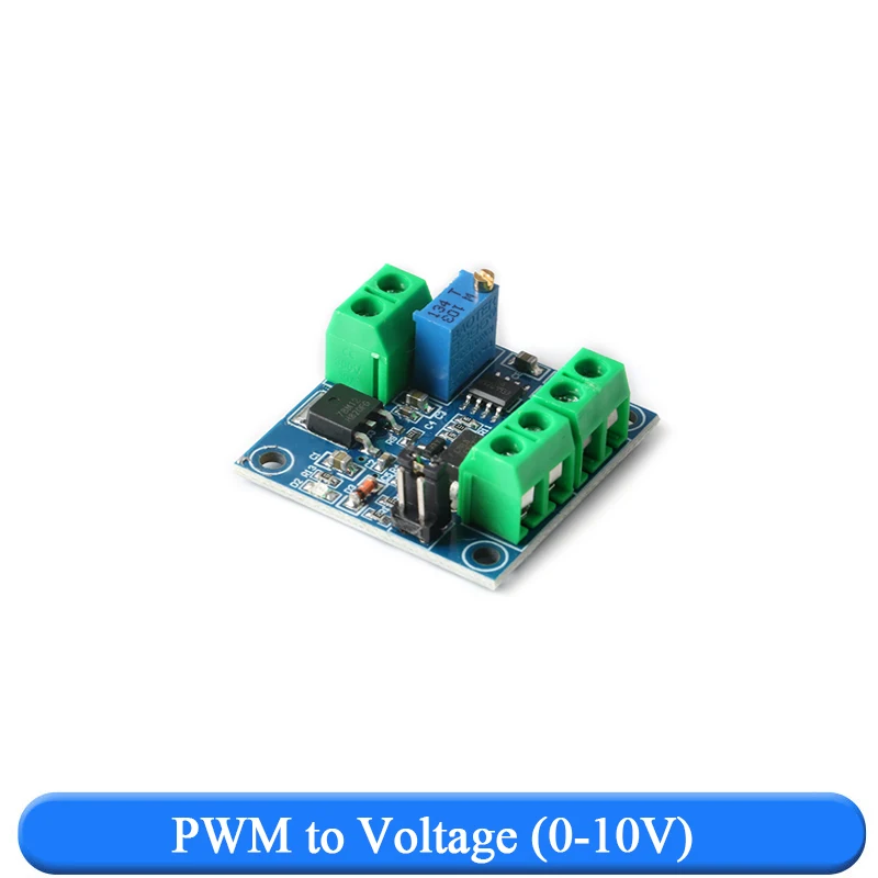
is_customized : YesUsage : SVCModel Number : Voltage to PWMCurrent Type : DCPhase : single phaseBrand Name : Stlxy : Mainland ChinaCertification : noneProduct introduction:This module is a module capable of converting voltage and PWM. The PWM digital signal is converted into 0 to 1OV analog signal. The output voltage is adjusted by the duty cycle of the entire PWM. V-PWM can convert 0-5V-10V voltage to 0%-100% PWM output, and adjust the PWM duty cycle by adjusting the voltage.Product parameter:PWM to voltage:Module working voltage: DC 12V-30V: (power power requirement: greater than 100MA)PWM signal receiving frequency range: 1KHZ-3KHZ:PWM signal input level range:Peak 4.5V to 10V level, jumper pin is inserted at 5V. This type of level signal is mainly aimed at the conventional industrial control card (such as MACH3 board) and the interface of 5V CPU;Peak 12 to 24V level, jumper pin inserted at 24V. This type of level signal is mainly aimed at the conventional PLC interface.Conversion range: 0%-1 00%PWM conversion to 0-10V voltageTolerance: 5%.Voltage to PWM:Module working voltage: DC 5V-12VOutput PWM frequency: about 50KHZPWM amplitude: 5VConversion range: 0-5V/0-10VVoltage conversion: 0%-100%6PWMTolerance: 1%-3%Pin description:PWM to voltage:VCC: Working power supply 12V-30V.GND: working power ground.PWM: Input the positive terminal of the PWM signal.GND: Input signal negative terminal.VOUT: output voltage 0-10VGND: output voltage ground.Voltage to PWM:VCC: Working power supply 5V-12V.GND: working power groundVIN: input voltage 0-10VGND: Input signal negative terminal.GND: Output PWM ground.PWM: output PWMInstructions for use:PWM to voltage:After power on, when there is no input signal, the output is 0v, and there is output only when there is input. When powering on for the first time, it is best to do a calibration and debugging: find a 50% duty cycle signal connected to PWM, GND, the amplitude corresponds to the relative jumper. The frequency is between 1KHZ-3KHZ. Use a multimeter to measure the two ports VOUT and GND. At this time, the meter is displayed at about 5V. Adjust the potentiometer on the board so that the multimeter is displayed at 5.00v. This calibrates your pulse signal Correspondence with this module. When the frequency changes, the corresponding relationship may be shifted and need to be recalibrated.The output voltage can be adjusted by adjusting the duty cycle.The accuracy can be controlled by adjusting the potentiometer.Voltage to PWM:Connect the working voltage to VCC and GND. Do not connect them in reverse to avoid damage to the board and devices. Connect a controllable voltage at the VIN terminal. The voltage range is divided into two types: 0-5V and 0-1 0V according to the selected mode. The PWM output is PWM. The duty cycle can be adjusted by adjusting the voltage. The accuracy can be controlled by adjusting the potentiometer
What’s in the box
1x packages
Specifications
- SKU: GE779HA5KBYZDNAFAMZ
- Model: SM-BXWDQ5-20-247
- Production Country: China
- Size (L x W x H cm): 20x10x20
- Weight (kg): 0.4
- Color: PWM to Voltage
- Main Material: other
Verified Customer Feedback

Customers who have bought this product have not yet posted comments
/product/36/4817533/1.jpg?5970)
Voltage to PWM Converter Module 0%-100% to 0-5V 0-10V Digital to Analog Signal PWM Adjustable Power Module
₦ 29,700
₦ 44,55033%
Questions about this product?

/product/36/4817533/1.jpg?5970)
